利用者:Kstar/一時保存/圧電センサ

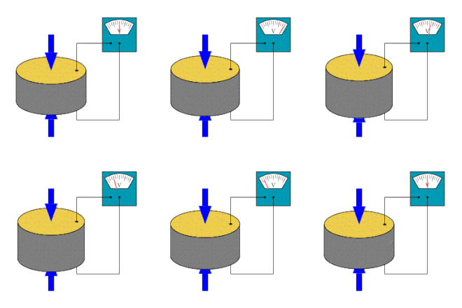
圧電センサ(英: Piezoelectric sensor)は、圧電効果を利用して圧力、加速度、ひずみや力を測定し、電気信号に変換するセンサ。
応用分野
[編集]
圧電センサは様々な過程の測定に使える多用途な道具であると分かってきた。品質保証、工程管理、および多くの産業における研究開発に使用されている。圧電効果は1880年にピエール・キュリーによって発見されたが、1950年代には既に産業用のセンサとして圧電効果は応用され始めた。それ以来、この測定原理はますます使用されており、極めて優れた特有の信頼性を伴う成熟技術と見なすことができる。圧電センサは医学・航空宇宙・原子力工学での計測器として、そして携帯電話のタッチパッドの圧力センサとして様々な用途に幅広く使用されている。自動車産業では、内燃機関を開発するときに燃焼をモニターするため圧電素子を使用する。センサは直接シリンダヘッドの追加口に取り付けられるか、または小型の圧電センサをスパークプラグやグロープラグに内蔵し取り付けられる。
圧電技術の向上は直接、圧電素子に備わった固有の利便性に関連する。多くの圧電性物質は他の多くの金属と比較して高い弾性率を有しており、10e6 N/m2に達する[疑問点]。圧電性のセンサは圧縮に反応する電気機械システムであるが、センサ素子はほとんど変形しない。これは圧電性のセンサが非常に頑丈であるためであり、広い入力電圧範囲にわたって非常に高い固有周波数と優れた直線形を持っている。さらに、圧電技術は電磁場と放射線に対する耐性が強く、過酷な状況の下で測定値を可能にする。圧電センサに使用されるいくつかの材料(特にリン酸ガリウム[1]やトルマリン)は高温でも高い安定性を保つことができ、最大1000℃の範囲まで動作可能である。トルマリンは圧電効果に加え焦電効果を示し、結晶の温度が変化するとき電気的信号を発生させる能力がある。この焦電効果は、圧電セラミック材料に共通の性質である。
| 原理 | 歪み感度 [V/μ*] | 閾値 [μ*] | 長さと閾値の比 |
|---|---|---|---|
| 圧電効果 | 5.0 | 0.00001 | 100,000,000 |
| 圧電抵抗効果 | 0.0001 | 0.0001 | 2,500,000 |
| 誘導性 | 0.001 | 0.0005 | 2,000,000 |
| 容量性 | 0.005 | 0.0001 | 750,000 |
圧電センサの問題点は、本当の静的な測定ができないということである。静的な力は圧電性物質内に一定量の電荷が発生させる。圧電センサが本来の圧力を読み取る動作ている間は、完全に絶縁されておらず、センサ内部の抵抗値が小さくなることによって、電子が一定量減少し、結果として出力信号が減衰する。高温になると内部抵抗と感度がさらに低下する。圧電効果での主な影響は、圧負荷の増加と温度によって、双晶形成による感度の減少がある。水晶を材料としたセンサは300℃より高い温度で測定を行う場合、冷却が必要となる一方で、GaPO4リン酸ガリウムのような特殊な結晶は、材料自体の融点まで全く双晶形成を示さない。
また、非常に高速な処理や周囲条件でのみ圧電センサが使用される場合、圧電効果は正しく働かない。しかしながら、実際は、ほぼ静的な測定を示すような様々な応用例があり、中には温度が500℃を超える利用例もある。
なお、圧電性のセンサは、自然界にも見られる。乾いた骨は圧電体であり、生物学的な力のセンサとして動作していると考えられている。
動作原理
[編集]圧電性物質がどの方向にカットされるかによって、横・縦・剪断の3つの主な動作モードに区別できる[3]。
- 横効果(Transverse effect)
- 力は中立軸(y)に沿って適用されます、そして、料金は(x)指示に沿って発生します、力線に垂直です。 充電量はそれぞれのピエゾ素子の幾何学的寸法に依存します。 寸法である、b、cは適用されます。
- A force is applied along a neutral axis (y) and the charges are generated along the (x) direction, perpendicular to the line of force. The amount of charge depends on the geometrical dimensions of the respective piezoelectric element. When dimensions apply,
- ,
- どこ、中立軸に沿った寸法、bによる. 5が中に軸とdを発生させるのが、対応する圧電性の係数であるという告発で立ち並んでいるということであるということであるか。
- where is the dimension in line with the neutral axis, is in line with the charge generating axis and is the corresponding piezoelectric coefficient.[1]
- 縦効果(Longitudinal effect)
- 生産された充電量は、厳密に適用された力に比例していて、ピエゾ素子の大きさ形状から独立しています。 機械的に連続的に、そして、電気的に平行な数要素を使用するのは、料金出力を増加させる唯一の方法です。 結果として起こる料金はそうです。
- The amount of charge produced is strictly proportional to the applied force and is independent of size and shape of the piezoelectric element. Using several elements that are mechanically in series and electrically in parallel is the only way to increase the charge output. The resulting charge is
- ,
- dxxがx-指示(pC/Nの)に沿って適用された力によって発表されたx-方向への料金のための圧電性の係数であるところ。 Fxはx-指示Nの適用されたForceです、そして、nは積み重ねられた要素の数に対応しています。
- where is the piezoelectric coefficient for a charge in x-direction released by forces applied along x-direction (in pC/N). is the applied Force in x-direction [N] and corresponds to the number of stacked elements .
- 剪断効果(Shear effect)
- 一方、作り出された料金は、厳密に適用された力に比例していて、要素の大きさ形状から独立しています。 機械的に連続的に、そして、電気的に平行なn要素のために、料金はそうです。
- Again, the charges produced are strictly proportional to the applied forces and are independent of the element’s size and shape. For elements mechanically in series and electrically in parallel the charge is
- .
縦、そして、剪断効果と対照して、横効果は適用された力の感度と要素の重要性について微調整する可能性を開きます。
In contrast to the longitudinal and shear effects, the transverse effect opens the possibility to fine-tune sensitivity on the force applied and the element dimension.
Electrical properties
[編集]
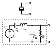
A piezoelectric transducer has very high DC output impedance and can be modeled as a proportional voltage source and filter network. The voltage V at the source is directly proportional to the applied force, pressure, or strain.[4] The output signal is then related to this mechanical force as if it had passed through the equivalent circuit.

A detailed model includes the effects of the sensor's mechanical construction and other non-idealities.[5] The inductance Lm is due to the seismic mass and inertia of the sensor itself. Ce is inversely proportional to the mechanical elasticity of the sensor. C0 represents the static capacitance of the transducer, resulting from an inertial mass of infinite size.[5] Ri is the insulation leakage resistance of the transducer element. If the sensor is connected to a load resistance, this also acts in parallel with the insulation resistance, both increasing the high-pass cutoff frequency.

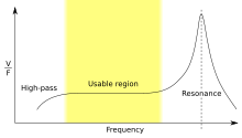
For use as a sensor, the flat region of the frequency response plot is typically used, between the high-pass cutoff and the resonant peak. The load and leakage resistance need to be large enough that low frequencies of interest are not lost. A simplified equivalent circuit model can be used in this region, in which Cs represents the capacitance of the sensor surface itself, determined by the standard formula for capacitance of parallel plates.[5][6] It can also be modeled as a charge source in parallel with the source capacitance, with the charge directly proportional to the applied force, as above.[4]
Sensor design
[編集]
Based on piezoelectric technology various physical quantities can be measured; the most common are pressure and acceleration. For pressure sensors, a thin membrane and a massive base is used, ensuring that an applied pressure specifically loads the elements in one direction. For accelerometers, a seismic mass is attached to the crystal elements. When the accelerometer experiences a motion, the invariant seismic mass loads the elements according to Newton’s second law of motion .
The main difference in the working principle between these two cases is the way forces are applied to the sensing elements. In a pressure sensor a thin membrane is used to transfer the force to the elements, while in accelerometers the forces are applied by an attached seismic mass.
Sensors often tend to be sensitive to more than one physical quantity. Pressure sensors show false signal when they are exposed to vibrations. Sophisticated pressure sensors therefore use acceleration compensation elements in addition to the pressure sensing elements. By carefully matching those elements, the acceleration signal (released from the compensation element) is subtracted from the combined signal of pressure and acceleration to derive the true pressure information.
Vibration sensors can also be used to harvest otherwise wasted energy from mechanical vibrations. This is accomplished by using piezoelectric materials to convert mechanical strain into usable electrical energy.[7]
Sensing materials
[編集]Two main groups of materials are used for piezoelectric sensors: piezoelectric ceramics and single crystal materials. The ceramic materials (such as PZT ceramic) have a piezoelectric constant / sensitivity that is roughly two orders of magnitude higher than those of single crystal materials and can be produced by inexpensive sintering processes. The piezoeffect in piezoceramics is "trained", so unfortunately their high sensitivity degrades over time. The degradation is highly correlated with temperature. The less sensitive crystal materials (gallium phosphate, quartz, tourmaline) have a much higher ? when carefully handled, almost infinite ? long term stability.
関連項目
[編集]参考文献
[編集]- ^ PIEZOCRYST GaPO4 Technology
- ^ Gautschi, G. (2002). Piezoelectric sensorics. Springer Berlin, Heidelberg, New York
- ^ “Piezoelectric sensors”. Piezocryst website. 2006年6月2日閲覧。
- ^ a b “Interfacing Piezo Film to Electronics” (PDF). Measurement Specialties (2006年3月). 2007年12月2日閲覧。[リンク切れ]
- ^ a b c Alfredo Vazquez Carazo (January 2000). Novel Piezoelectric Transducers for High Voltage Measurements. Universitat Politecnica de Catalunya. pp. 242.
- ^ Karki, James (2000年9月). “Signal Conditioning Piezoelectric Sensors” (PDF). Texas Instruments. 2007年12月2日閲覧。
- ^ Ludlow, Chris (2008年5月). “Energy Harvesting with Piezoelectric Sensors” (PDF). Mide Technology. 2008年5月21日閲覧。 [リンク切れ]
外部リンク
[編集]- Material constants of gallium phosphate
- Langatate - new material for high-temperature piezoelectric sensors
- Piezoelectric multilayer sensors
- Spark-Plug with integrated miniaturized piezoelectric pressure sensor
- Overview of piezoelectric pressure sensors for automotive engine development
- Using the Piezoelectric Effect in Sensors
- Using a piezoelectric sensor to create a vibration sensor.
- COMSOL Composite Piezoelectric Transducer FEA Model
- Piezo Systems: Introduction to Piezoelectric Transducers - 多くの図解


